Now that we have set the machine up and created our sensors it is time to start measuring. The DMIS language requires that the programmer use a feature based system in order to measure and this means that you have to define a feature before measuring it. The most common types of feature are:
POINT, ARC, CIRCLE, CYLNDR, SPHERE, CPARLN (slot), LINE, PLANE, CONE, GCURVE and GSURF.
Other less common types of feature like TORUS and ELLIPS are also available. Refer to the DMIS standard for all available features.
Format of a point definition:
F(name)=FEAT/POINT,CART or POL, X(R),Y(A),Z(H),I,J,K
A point requires a name, coordinate type, position and direction (refer to the article about sensors for more information regarding vectors). If the coordinate type is CART then the position values are X, Y, Z. If the coordinate type is POL the position values are R, A, H as defined by the current working plane.
The current working plane is set using the WKPLAN statement. This statement is a setting but was not included in the ‘Getting Started’ article because it changes throughout a program so that you can measure various features in different directions.
The working plane statement:
WKPLAN/XY or YZ or ZX
Format of a circle definition:
F(name)=FEAT/CIRCLE,INNER or OUTER,CART or POL,X(R),Y(A),Z(H),I,J,K,D
A circle is similar to a point but requires an extra keyword to determine whether the circle is a bore or shaft and has an extra value to specify the size of the circle.
Format of a line definition:
F(name)= FEAT/LINE,BND or UNBND,CART or POL$
,X1 or X,Y1 or Y, Z1 or Z$
,X2 or I1,Y2 or J1, Z2 or K1$
,I or I2, J or J2, K or K2
This definition format can be a little confusing. It can be defined in two different ways, the BND option requiring you to specify the ends of the line as coordinates and the direction of the plane the line lies in (the normal) and the UNBND option requires the center, direction and plane. Obviously, X, Y & Z would become R, A & H if the POL option was used and the correct working plane would need to be set. You may also have noticed that there is $ sign at the end of some of the code lines. This means that the command continues on the next line and is used when DMIS commands exceed 80 characters.
Refer to the DMIS standard or ‘Step by Step DMIS Programming’ for further examples of DMIS feature definitions.
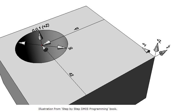
A CIRCLE definition:
F(CIR001)=FEAT/CIRCLE,INNER,CART,-40,42,0,0,0,1,30
As previously discussed, the feature definition describes what the feature should measure (the specification) but is not a measurement. The values entered in the definition will be used as nominal’s against which the measured features will be compared when reporting. This means that the feature definition needs to be precise. In some cases the values will be used to drive automatic measurement of the feature (more about that later) but in all cases the values will be used to guide the measurement routines as they create the measured feature. The CIRCLE definition above defines a circle called CIR001. CIR001 is a hole (INNER) whose first three values (X=-40, Y=42, Z=0) are in cartesian coordinates (CART) and represent the position of the circle in relation to the current part axes system. The next three values (I=0, J=0, K=1) represent the direction the circle faces and the last value (D=30) is the size or diameter of the circle.
Once a feature has been defined you can measure it using the MEAS and ENDMES statements.
A measurement command or block:
MEAS/feature_type,F(name),num_points
.
.
.
ENDMES
A measurement block starts with a MEAS statement and ends with a ENDMES statement. The space between is reserved for path statements but can be empty.
A CIRCLE measurement:
MEAS/CIRCLE,F(CIR001),4
ENDMES
What happens at this point depends on the current MODE setting. If you have the mode set to MODE/MAN, the CMM will prompt you to take 4 points inside the hole. The type of prompt is not covered by the DMIS standard and will vary from machine to machine. If the mode is set to MODE/AUTO,PROG,MAN and the manufacturer has created an automatic measurement routine for circles the CMM will use the settings we discussed previously to automatically measure the circle based on that routine using the number of points in the measure statement combined with the values in the definition. If the mode is set to MODE/PROG,MAN or the manufacturer did not create an automatic measurement routine you will have to add a measurement path in the form of touches and moves between the MEAS and ENDMES statements. MODE/PROG,MAN measurements do not use all of the SNSET settings mentioned in previous articles so you can’t rely on SNSET/CLRSRF to move clear prior to measurement. SNSET/APPRCH, SNSET/RETRCT and SNSET/SEARCH will still apply.
A MODE/PROG,MAN CIRCLE measurement:
MEAS/CIRCLE,F(CIR001),4
GOTO/-40,42,10
PTMEAS/CART,-25.0000,42.0000,0,-1.000,0.000,0.000
PTMEAS/CART,-40.0000,57.0000,0,0.000,-1.000,0.000
PTMEAS/CART,-55.0000,42.0000,0,1.000,0.000,0.000
PTMEAS/CART,-40.0000,27.0000,0,0.000,1.000,0.000
GOTO/-40,42,10
ENDMES
This measurement block contains moves and touches because it is executed in MODE/PROG,MAN mode. If this block was executed and did not contain the path statements the system would have no choice but to treat it as a manual measurement and prompt the operator to take the number of points specified in the MEAS command. You can put as many touches inside the measure block as required, the number of touches in the MEAS statement will be ignored. The path contains two DMIS statements we haven’t discussed before.
Format of a go to statement:
GOTO/X,Y,Z or GOTO/POL,R,A,H or GOTO/INCR,Dist,I,J,K
In the first instance the move would be to a position from the current part datum as specified by X, Y & Z. In the second instance the move would be to a position from the current part datum as a radius, angle and height as determined by the current working plane. The last instance is an incremental move from the current position by an amount defined by Dist along a direction defined by I, J & K.
Format of a path point statement:
PTMEAS/CART or POL,X(R),Y(A),Z(H),I,J,K
The PTMEAS statement is a special point measurement that can only be used inside measurement blocks.
For other DMIS statements that can be used inside of measurement blocks refer to the DMIS standard.
Another version of the measure statement is available under the DMIS standard and is used when feature location planes vary. This version of the measurement command is popular in sheet metal and plastic manufacturing areas and is referred to as relative measurement.
Format of a relative measurement statement:
RMEAS/feature_type,F(name),num _points,F or FA(name)
or
RMEAS/feature_type,F(name),num _points,VECBLD,radius,num_points
The first example of the RMEAS format requires that you previously define or measure a feature and the position of that feature will determine the height and orientation (where applicable) at which this feature will be measured. The second example will take extra touches on the surface around this feature to adjust the height and if three or more points are taken, the orientation of this feature. The points are controlled by the radius value from the outer edge of the feature and the num_points option. The RMEAS measurement must be followed by the ENDMES statement in the same way as a standard measurement.
At this point it is worth giving a note of caution. Certain features such as points, circles, lines, etc. are calculated using their defined vector direction which is assumed to be correct. If the part is in error or the current part datum is misaligned these measurements will report results based on the bad direction rather than the actual part. Three dimensional features such as cylinders, planes, spheres, etc. do not rely on the definition because they can create themselves independently. This means that the center and form of a cylinder will be better than a circle if the actual features do not lay in the specified direction. If in doubt you must perform localized orientation using the relative measure options or the datum techniques we will be covering in future articles.
Stephen Horsfall specializes in DMIS programming, training and consulting and is the author of ‘Step by Step DMIS Programming’. He can be at contacted at steve.horsfall@cmmts.com.