There are no direct datum measurement commands contained in the DMIS language so this article will build on the previous ones by using features we would have already measured or constructed to create them. The reason we create datums, sometimes referred to as coordinate systems, is so that we can report valid feature positions from a known origin in up to three dimensions. The orientation of the coordinate system will also have a direct effect on the shape of some features when analyzed. DMIS’ various datum statements allow us to define the orientation and position of the axes and planes that make up the coordinate system. When you create a datum you use features to define the direction and position of three scales that are square to each other. Each scale comprises an axis that will lie along the direction of the datum feature and a plane that is square to that scale, passing through the scales zero point. Because of their close relationship with CAD systems, DMIS datums are always right handed.
The primary command for creating a datum is the DATSET statement which allows you to enter up to three datum features in order to dictate the coordinate systems’ axes directions and optionally its origin:
D(DAT1)=DATSET/DAT(A),ZDIR,ZORIG,DAT(B),YDIR,YORIG,DAT(C),XORIG
The example above creates a datum called DAT1 using A as the primary datum Z, B as the secondary datum Y and C as the tertiary datum X (origin only). The DATSET statement is peculiar in that it does not allow you to refer to features directly. This means that A, B and C are datum references (as indicated by the DAT prefix) which must already have been associated with features using the DATDEF statement like this:
DATDEF/FA(FACEZ),DAT(A)
DATDEF/FA(FACEY),DAT(B)
DATDEF/FA(FACEX),DAT(C)
The reasoning here is that DMIS datums are closely associated with GD&T which makes using the letters shown in tolerance boxes on drawings rather than feature names logical.
Below is an example of a one axis datum created by the DATSET statement. This code creates a full three axes datum by aligning the current Z axis along the direction of the feature called ‘Primary_Face_A’. It also places the Z axis zero at the faces average position. Although they are not shown in the picture, the remaining coordinate system axes will be re-oriented around their current positions so that they are square to the new Z axis and plane.
DATDEF/FA(Primary_Face_A),DAT(A)
D(DATUM1)=DATSET/DAT(A),ZDIR,ZORIG
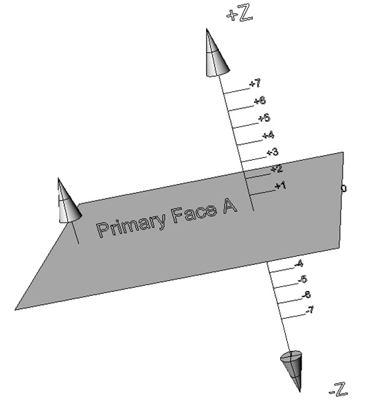
The feature used for this example would be a plane and as you can see it is the direction of the plane that defines the primary axis orientation. This orientation would be in the form of rotations around the current X and Y axes.
A two axis DATSET:
DATDEF/FA(Primary_Face_A),DAT(A)
DATDEF/FA(Secondary_Face_B),DAT(B)
D(DATUM2)=DATSET/DAT(A),ZDIR,ZORIG,DAT(B),XDIR,XORIG
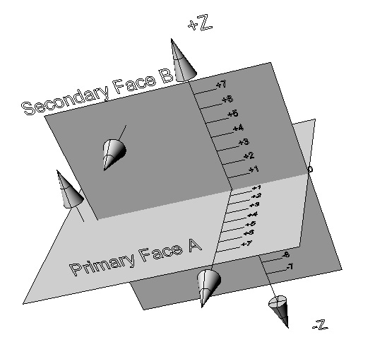
The example above uses the same face for its primary datum but follows that with a reference to a datum called B which points to a feature called ‘Secondary_Face_B’. The direction of ‘Secondary_Face_B’ is used to set the secondary X axis and plane by rotating them around the Z axis until they are parallel with the face direction. This is sometimes referred to as the timing rotation and because the B plane must be square to the A plane when viewed along the Y axis there will not be any rotation in that view.
Although the previous example is a two axis datum it is all you need to provide full rotational control of the coordinate system because the tertiary axis and plane will be created square to the other two. The only thing missing is the position of the last plane along the Y axis:
DATDEF/FA(Primary_Face_A),DAT(A)
DATDEF/FA(Secondary_Face_B),DAT(B)
DATDEF/FA(Tertiary_Face_C),DAT(C)
D(DATUM3)=DATSET/DAT(A),ZDIR,ZORIG,DAT(B),XDIR,XORIG,DAT(C),YORIG
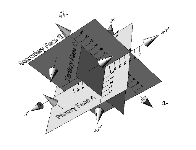
As you can see, all I have done for this example is to add datum C (feature ‘Tertiary_Face_C’) as the YORIG to the end of the DATSET statement to give me a 3D fully located measurement envelope.
The previous examples assume that the component being measured is of a prismatic nature and that the features referenced in the datums were faces. This is obviously not always the case and datums can be constructed from many different feature types, the example below creates a coordinate system using a mixture of a cylinder, a line and a face:
DATDEF/FA(A-CYLINDER), DAT(A)
DATDEF/FA(LINE-A-B), DAT(A-B)
DATDEF/FA(B-PT1), DAT(B)
D(AB)=DATSET/DAT(A),XDIR,DAT(A-B),YDIR,DAT(B),XORIG,YORIG,ZORIG
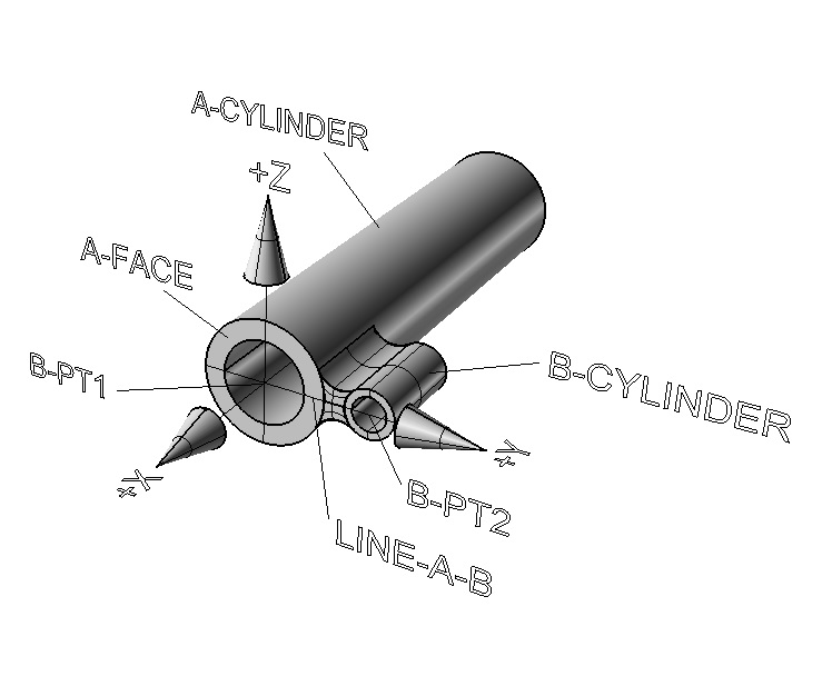
This example uses the main cylinder (A-CYLINDER) to set the primary X axis. A line (LINE-A-B) constructed through the intersection of the cylinders and face (B-PT1 & B-PT2) defines the secondary Y axis or timing direction. The axis zero positions are all set using the intersection of the main cylinder and the face (B-PT1).
It should be obvious from this example that you do not need faces to create datum planes because they are a product of the datum axes and pass through its zero point. It should also be obvious that each datum does not need to create an origin. The only rule here is that you can’t repeat an origin but you are free to omit them or assign them all to a single datum.
The DATSET statement is not the only DMIS command used to manipulate the coordinate system. You can also use the TRANS and ROTATE commands. The TRANS command is used to move the zero point along an axis. You can use this command to move to a feature or datum reference (both these examples have the same effect):
D(TRANS-DAT_FTRS)=TRANS/XORIG,FA(B-PT1),YORIG,FA(A-CYLINDER),YORIG,FA(A-CYLINDER)
D(TRANS-DAT_DTMS)=TRANS/XORIG,DAT(B),YORIG,DAT(A),ZORIG,DAT(A)
or by a value:
D(TRANS-DAT_MOVE)=TRANS/XORIG,-25.75,ZORIG,10.0
or by the current probe radius:
D(TRANS-DAT_PRBY)=TRANS/YORIG,PRBRAD
As you probably noticed from the examples, the TRANS statement allows you to alter the origin of one or more axis simultaneously by adding them to the parameter list.
The ROTATE statement is used to rotate around an axis either by value:
D(ROTATE-DAT_VAL)=ROTATE/ZAXIS,-45.0
or to a feature:
D(ROTATE-DAT_FTR)=ROTATE/XAXIS,FA(LINE-A-B),YDIR
These commands represent the separate components of the DATSET statement (DIR and ORIG) and give you more control of the process as individual elements. It wouldn’t make sense to try and use the ROTATE command to create a primary axis which is what the DATSET was designed to do but you could mix the DATSET, ROTATE and TRANS statements because, as mentioned previously, the secondary orientation and all origin parameters are optional. Here is another version of the previous cylinder datum that uses the DATSET as single axis datum:
DATDEF/FA(A-CYLINDER), DAT(A)
DATDEF/FA(LINE-A-B), DAT(A-B)
DATDEF/FA(B-PT1), DAT(B)
D(PRE_AB)=TRANS/XORIG,DAT(B),YORIG,DAT(B),ZORIG,DAT(B)
D(A)=DATSET/DAT(A),XDIR
D(AB)=ROTATE/XAXIS,FA(LINE-A-B),YDIR
In the above example I translate all three datum origins to the intersection of the main plane and the front face (B-PT1). I then use the DATSET statement to set the X axis parallel with the primary cylinder (A-CYLINDER), finally rotating around to line up the secondary Y axis with the line constructed from the intersection of the cylinders and A-FACE (LINE-A-B).
Note … The direction of the feature dictates which direction the datum axis will point so we assume that the primary cylinder direction is from rear to front in the example. If the reverse were true we could still get an X primary to point forward by changing the DATSET statement to read:
D(A)=DATSET/DAT(A),-XDIR
Likewise, a reverse in the direction of the timing line (LINE-A-B) would result in a change to the ROTATE statement to keep the datum axis as drawn:
D(AB)=ROTATE/XAXIS,FA(LINE-A-B),-YDIR
If the datum you created gets overwritten the DMIS language provides you with the RECALL statement so that you don’t have to re-creating it:
RECALL/DA(AB)
DMIS also contains a SAVE option which is generally used to save a datum to an external device for later retrieval. Most systems don’t require you to save a datum in order to recall it providing you don’t close the program.
The commands mentioned in this article provide you with the tools needed to create feature based datums, however with the measurement of complex surface comes challenges that are hard to overcome using these statements which is why DMIS contains the LOCATE, ITERAT and MATDEF commands. These commands give you access to complex best fitting algorithms but due to their complex nature can’t be included in this article. For further information and examples refer to the our ‘Step by Step DMIS Programming’ book or the DMIS Standard.
Stephen Horsfall specializes in DMIS programming, training and consulting and is the author of ‘Step by Step DMIS Programming’. He can be at contacted at steve.horsfall@cmmts.com.