This article builds on the previous overview and gives you some examples of program structure along with suggestions regarding some ‘must have’ settings to get your program underway.
Most DMIS based CMM’s provide icon based tools to create DMIS programs, however a DMIS programmer does not need CMM software to create a DMIS program. DMIS programs can be created from any text editor and the program can usually be opened by or imported into the CMM software later. It should be noted however that a text editor works well when you are measuring primitive features or making simple changes using engineering drawings but will not suffice if you need data from a CAD model in order to measure complex surfaces or simulate your measurement routines. These types of tasks are best left to a professional CMM system.
A DMIS program that does nothing:
DMISMN/’EXAMPLE OF A PROGRAM SHELL’,4.0
$$
$$
$$ this program does nothing
$$
$$
ENDFIL
The example above isn’t very useful but does illustrate a starting point for programming. The first and last lines are generally regarded as compulsory and define the start and end of the program. The DMISMN statement includes a text area that can be used to provide a description of the program and a DMIS version number. Some CMM’s use this DMIS version number to check a program’s syntax. The ENDFIL statement signifies the end of the program. These two commands provide two examples of the language. DMISMN starts with a command (the DMIS standard refers to this as the ‘major word’) and is followed by two parameters whereas the ENDFIL is a single command with no parameters. Notice the forward slash ‘/’ between the DMISMN command and the rest of the line. This is common to all DMIS statements that contain parameters and serves as a separator between the major word and the parameters or minor words (more about those later). All other lines in this program are programmers comments because they start with $$. DMIS programmers should consider using comments at strategic points inside the program to provide information that will help others to understand the code. These comments will also provide information to jog your memory and help you to maintain the program.
A DMIS program containing typical settings:
DMISMN/’EXAMPLE OF PROGRAM SETTINGS’,4.0
$$
$$ Program Name: ABC123.DMI
$$ Author : Steve Horsfall
$$ Date Written: 11/23/08
$$
$$ **** Start of Settings ****
$$
UNITS/MM,ANGDEC
$$
SNSET/APPRCH,5
SNSET/RETRCT,1
SNSET/CLRSRF,15
SNSET/DEPTH,3
SNSET/SEARCH,20
$$
FEDRAT/POSVEL,MPM,1
FEDRAT/MESVEL,MPM,0.1
$$
PRCOMP/ON
$$
D(CMM)=DATSET/MCS
$$
$$ **** End of Settings ****
$$
$$
ENDFIL
This example shows a number of DMIS statements a programmer should consider including to ensure that the CMM is properly set up prior to measurement or movement. All settings are considered to be modal which means that once they are set they will apply to future measurement and move commands until they are changed or until the program terminates. After the program terminates there is no guarantee that the CMM will remember the settings which makes it all the more important to include them in all programs you write.
The UNITS commands sets the units of measurement. Not surprisingly the first parameter is the MM command (the DMIS standard refers to commands that follow the ‘/’ as ‘minor words’) which sets the CMM to metric mode. Unlike many other CMM languages this is followed by the ANGDEC minor word which sets the units for angular measurement. Refer to the DMIS standard for the options available for these minor words. This setting also has an optional minor word for setting the temperature units.
The SNSET settings control the sensor movement during automatic inspection and use measurement position and direction as references. APPRCH sets the distance the sensor will travel at touch speed prior to reaching the specified measurement position. RETRCT sets the distance that the sensor will back off once contact is made with the part. SEARCH sets the distance the sensor will travel at touch speed before giving up. CLRSRF sets the clearance distance the sensor will use prior to continuing on to the APPRCH position. In the form shown this setting will use the next measurement as a guide to direction and origin. You can also specify a reference feature as a parameter of the command which will control the direction and origin. DEPTH is the distance the sensor will travel into an applicable feature before measurement takes place (always applied in the opposite direction of the features).
The FEDRAT settings control the speed of the CMM and are split into two types of speed, POSVEL controls the speed of the CMM while it is moving from measurement to measurement while MESVEL controls the speed of the CMM while searching for a measurement (in other words, while it is inside the APPRCH/SEARCH zone). Both these settings are controlled using the MPM minor word which stands for meters per minute. From a programmers point of view meters per minute is a pretty abstract concept and if you’re anything like me you will need a little trial and error to figure out what one meter per minute means. Some systems do not let you change POSVEL directly by value in which case you can use the PCENT option to set the CMM speed as percentage of the configured maximum speed (where 0.5=50% and 1.0=100%). This can be useful for safety during prove out of a program or where space is tight. MESVEL should be set only at the start of the program and not changed. Changes to the MESVEL setting during program execution may cause measurement inconsistency depending on probing. The value assigned to this setting will almost always be dictated by the probe and CMM types and programmers would do well to follow the CMM manufacturer’s guidelines in these areas.
Although they are not included in my shell the DMIS language provides commands for setting the acceleration of the CMM under the ACLRAT command using the POSACL and MESACL minor words. These settings are similar in nature to the FEDRAT settings and likewise are very machine specific. The acceleration values are usually left to the CMM configuration but if you want to write a truly portable program they should be included in your shell.
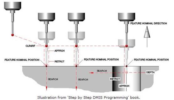
The previous illustration shows the effect the setting statements have during measurement of various features. In this example the sensor moves from its current position to the CLRSRF position above the feature as defined by the feature’s nominal position and direction using POSVEL. It then continues at POSVEL towards the feature until it reaches the APPRCH distance. The sensor continues from this position at MESVEL until the sensor touches the part or reaches the SEARCH distance at which point the CMM will stop and report an error. If the sensor touches the part it backs off in the opposite direction by the RETRCT distance. The second surface point follows the same procedure whereas the circle measurement is slightly different. In the case of the circle measurement the CLRSRF position is the same as the point assuming the nominal center of the circle is at the face. The sensor then travels at POSVEL until it reaches the current DEPTH distance past the circle nominal. The CMM will then search for each point within the circle using APPRCH and SEARCH in the same way that points were measured.
I have included two other DMIS commands in my settings section that you should consider adding to you own programs. The PRCOMP setting provides the ability to turn the probe compensation on or off. This is an important setting because if you turn it off or if it is left off by someone else, all measurement results will be recorded from the probe center. I’ll cover probe compensation more fully in future articles on measurement. Finally I have included the DATSET statement which returns the orientation and origin of the CMM axes to native positions. This command is a little different to the others in the example code because it is an assignment. What this means is that the command does not start with the major word, it starts with the name of a datum called CMM which is assigned using the major word DATSET and the minor word MCS. I’ll cover datums more fully in future articles.
Although my example program is fairly brief it should be enough to get you started and provides some examples of DMIS code. Feel free to use this example and build on it and future examples when creating your own DMIS programs.
Stephen Horsfall specializes in DMIS programming, training and consulting and is the author of ‘Step by Step DMIS Programming’. He can be at contacted at steve.horsfall@cmmts.com.