Over previous articles I have written about specific DMIS language features and the syntax used to implement them. In this article I will cover the more general subject of good programming practices. Although good programming practices are highly subjective and deadlines generally mean we seldom implement them all, programmers should make an effort to incorporate as many of the ideas presented in this article as possible. These ideas may add some time to the initial program creation but can save many more hours later when it comes to maintaining those programs
Getting Started:
When starting an inspection program it’s a good idea to get an overview of the drawings and other related documents, especially datum structures. Getting the ‘big picture’ will allow you to formulate an overall plan based on the various dependencies you find within those documents. Although getting an overview of the project is essential, do not try to get to specific or try to create the whole program in your mind. If the parts being measured are of a complex nature you will run the risk of confusing yourself. Instead try to concentrate on areas of the program which will depend on others so that you can start to create an order in which the various tasks will be accomplished. Divide and conquer!
Creating a Program Starting Shell or Template:
The first task in any program is to set up the machine by initializing all variables that may affect the inspection process. If the program is going to be measured in AUTO mode this is even more important. A good programmer will have already created a shell or template in order to start all new programs. This template should include such variables as machine speeds, approach, clearance, depth, retract, etc. The shell can also include output details, sensor definitions and tolerances:
DMISMN/’Program Start Teplate’,05.2
$$
$$ output options
$$
UNITS/INCH,ANGDEC
DECPL/ALL,4
V(ALL)=VFORM/ALL
DISPLY/TERM,V(ALL),STOR,V(ALL)
$$
$$ general tolerances
$$
T(X100)=TOL/CORTOL,XAXIS,-0.1,0.1
T(X020)=TOL/CORTOL,XAXIS,-0.02,0.02
T(X010)=TOL/CORTOL,XAXIS,-0.01,0.01
$$
T(Y100)=TOL/CORTOL,YAXIS,-0.1,0.1
T(Y020)=TOL/CORTOL,YAXIS,-0.02,0.02
T(Y010)=TOL/CORTOL,YAXIS,-0.01,0.01
$$
T(Z100)=TOL/CORTOL,ZAXIS,-0.1,0.1
T(Z020)=TOL/CORTOL,ZAXIS,-0.02,0.02
T(Z010)=TOL/CORTOL,ZAXIS,-0.01,0.01
$$
$$ CMM Settings
$$
$$
SNSET/RETRCT,0.02
SNSET/SEARCH,1
SNSET/CLRSRF,0.2
SNSET/APPRCH,0.075
SNSET/DEPTH,0.02
$$
$$ sensors
$$
RECALL/S(T1_0+0)
RECALL/S(T1_90+90)
RECALL/S(T1_90+15)
RECALL/S(T1_90-15)
RECALL/S(T1_90-90)
RECALL/S(T1_45+0)
RECALL/S(T1_45+90)
RECALL/S(T1_45-90)
RECALL/S(T1_45+135)
RECALL/S(T1_45+180)
RECALL/S(T1_45-135)
RECALL/S(T1_45+45)
RECALL/S(T1_45-45)
$$
$$
$$ program goes here
$$
$$
ENDFIL
Program Comments:
As you can see in the program listing above adding comments explaining program decisions and logic makes the code more readable. It is up to you, the programmer to decide when it is logical to add comments and when it is not. Bear in mind that you may forget over time the purpose of complicated sections of code or you may have to hand the program over to a less experienced user. It is also a good idea to separate code lines using comments even when no description is inserted:
$$
GOTO/CART,9.354,-2.636,1.332
$$
SNSLCT/SA(T1_90-90)
$$
GOTO/CART,12.465,-7.037,5.267
$$
Code can be separated using spaces but programmers should be aware that some parsing routines and utilities have a habit of removing white space from programs. This shouldn’t happen if you use comments.
If you give some thought to how you name features and datums in a program it may minimize the need for as many comments.
Following the Drawing Dimensions:
Making sure that the program follows the drawing during measurement can help someone reading the program to understand what is happening. An example of logical use of the drawing is a programmer who manipulates the datum system to drive measurement using drawing dimensions. Typically this is required when a drawing uses chained dimensions, requiring the programmer to measure one dependent feature which is then used as a location before moving to the next feature dimensioned from it:
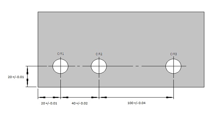
In the example above it is logical to datum on the lower left corner before measuring and outputting CIR1. The programmer should then translate the horizontal (left to right) axis of the current datum so that zero moves to the actual center of CIR1 before measuring and outputting CIR2 and so on.
Some programmers like to collect all data before creating results that represent the drawing dimensions which although is not incorrect makes maintenance of the data collection code harder. For example if a dimension changes in the middle, all subsequent code requires change. If logical movement of the datum had been utilized only one measurement needs to be changed. Quite apart from this obvious advantage the code is very hard to follow if feature dimensions do not follow the drawing.
Alignment:
The type of part alignment will vary depending on how your CMM is configured. Some machines will have dedicated fixtures that locate the part at the same point and in the same orientation every time they are loaded. In these cases the programmer can offset the starting origin and go straight into AUTO mode in order to start the part setup phase. I am assuming here that the fixture is purely a holding device rather than a certified locater that substitutes for a part alignment. If the part is not accurately located the programmer will have to ask the user to collect data in manual mode in order to tell the CMM where the part is. It is a good idea to limit user interaction to a minimum in order to stop human error infecting the alignment process. If the holding fixture orients the part well enough a partial alignment might suffice but if there is any doubt as to the accuracy of the part placement a full manual setup must be carried out. It is worth mentioning here that if parts are placed on the machine in a fashion that dictates a full manual setup then they may be so out of square that measurement sequences perform badly due to probe shanking (when a touch contacts the stem of the stylus rather than the tip). In any case the CMM needs to be made aware of the position of the part before you can place it into AUTO and start the final alignment. Depending on the integrity of the fixture location or your faith in the manual measurement process it may be necessary to automatically align more than once. The final datum is sometimes preceded by a simple pre-datum in order to make sure that the features measured in the final alignment are always measured in the same place. It could be argued that touching a feature anywhere on the datum features creates a valid measurement but a pre-alignment ensures repeatability between one measurement cycle and the next. Obviously the alignment task will be driven by the part drawings and related documents or in the absence of specified datum call outs, common sense.
Measurement:
The path of a given measurement should be analyzed to determine the surface coverage required to calculate any given feature. For example a machined bore with a form tolerance requires more touches than a sheet metal hole with wide open tolerances for diameter and position. In the case of a sheet metal hole you may need to employ the DMIS RMEAS function in order to sample the face around the hole prior in order to orient and locate the measurement. There is no hard and fast rule regarding the surface coverage of a given feature and most programmers use experience to determine this variable. One consideration would be the repeatability of the CMM. If the equipment is old and prone to bad repeatability it is a good idea to take more rather than less touches in a given feature. This will give a better average and negate bad touches.
Output:
When designing output the programmer should consider the target audience and create reports accordingly. For example, if the results are destined for the production line it is a good idea to make sure that the axes directions match the CNC machines axes. If the target audience is just looking for a pass or fail, try to design the output so that they don’t have to read pages of results looking for something in the error column of a standard print out. A simple red or green signal would suffice or a summary. You can always provide more detail if something is in error.
General Tips:
There are also some general considerations when creating inspection routines. One area to watch is the use of sub routines and high level functions. A general rule of thumb is that you should keep a program as simple as possible avoiding high level functions where possible. This will make future maintenance far easier, especially for programmers less experienced than you. The use of sub routines makes it harder to distribute and keep track of the program. Sub routines are however very useful when it comes to eliminating redundant code and should be used to split highly complex code into more manageable pieces. High level code has its place but should not be used gratuitously and when used it should be documented fully using programmers comments.
If you are lucky enough to have data and tools that allow offline simulation it is a good idea to not only simulate safety but also check the program execution against CAD data. One way to do this is to manipulate the part datum in such a way that you line it up with CAD features as dictated by the drawing. If you have used the DMIS tools to manipulate the datum so that the axes should line up with a CAD face, picking that CAD face should return a zero location and perfect vectors. If it does not return these results you know you have a problem. If however you choose to assume that your alignment is correctly constructed and go ahead and select 3D measurement points that can’t be traced to the drawing you can’t tell if they are correct and they make very little sense when reading the program for later maintenance.
A programmer must try to balance efficiency and program perfection with cost. In any case there is no such thing as a perfect program so the aim is to create a process that is as efficient as possible and easy to maintain based on the time available.
Stephen Horsfall specializes in DMIS programming, training and consulting and is the author of ‘Step by Step DMIS Programming’. He can be at contacted at steve.horsfall@cmmts.com.