In the previous article we created a shell with relevant settings for our program. Now we must define and calibrate the sensor we would like to use for inspection.
Sensors are sometimes referred to as probes and usually consist of a head, trigger device and one or more styli. Depending on the manufacturer of the head it will be either fixed or have the ability to rotate. If the probe is fixed it will usually have multiple styli attached to provide access to different areas of a component. An indexing head provides a manual or automatic rotary axis allowing the user to move the head for part access with a single styli (although more styli are an option):
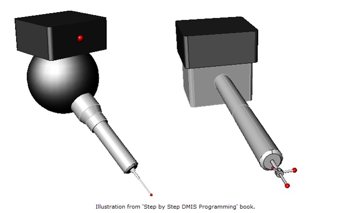
The sensor on the left is an indexing head while the one on the right represents a typical fixed head. Both heads have a single trigger device but, as is typical, the fixed head has more styli than the indexing head. Whichever type of head you are using, you will need to describe its attributes to the inspection system prior to use by defining it.
A typical fixed head definition:
S(TIP1)=SNSDEF/PROBE,FIXED,CART,250,15,-50,0,0,1,3
This definition describes a probing system as FIXED using CART (rectangular) coordinates.
The name of the sensor is TIP1 which is offset 250 from the sensor centerline in the X direction, 15 along the Y axis and -50 from the head mounting surface in the Z direction.
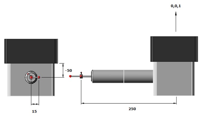
The next three parameters (0,0,1) describe the direction the head is mounted to the CMM. The direction is specified as angles related to the X, Y & Z axes in the form of vectors. Vectors are used extensively in the DMIS language so now is a good time to talk a little more about them. Vectors, sometimes referred to Euclidean Vectors, are the means by which DMIS defines a direction in 3D space. Unlike some measurement systems which restrict measurements to 2D or ‘in-plane’, DMIS allows the user to describe elements of the measurement system as a 3D direction which gives greater flexibility and provides a better relationship between DMIS and CAD. A vector defines magnitude and direction and is made up of three numbers, often referred to as I, J & K. These numbers represent the distance traveled along the X, Y & Z axes to reach a position of specified magnitude along a direction. Although the magnitude is not important it is usually defined as a unit length of 1 in whatever units are being used.
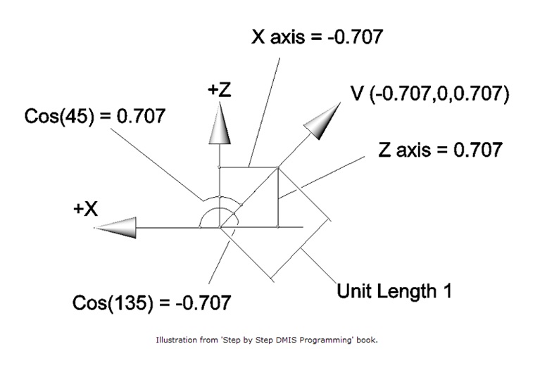
As you can see in the previous illustration, when you travel at 45 degrees in the Y plane for 1 unit the amount traveled along the X & Z axes is 0.707 (rounded up). The X axis is negative because the direction was away from the positive direction of the X axis. The Y axis is zero because there was no movement in Y. The head direction is I=0, J=0, K=1 which is the same as saying that the head direction traveled 0 along X, 0 along Y and 1 along Z. This means that the head is mounted in the Z+ direction (Z- would have been 0, 0, -1).
The final value in the sensor definition is the diameter of the stylus’ sphere. It is assumed to be a sphere in the absence of a minor word to describe the stylus type as another shape, such as a cylinder.
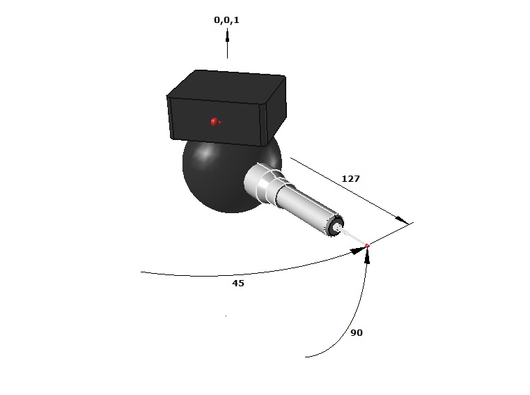
A typical indexing head definition:
S(TIP1)=SNSDEF/PROBE,INDEX,POL,90,45,0,0,1,127,2
This definition is more common and describes a probing system as INDEX using POL (polar) coordinates. As in the previous example the name of the tip is TIP1. The next two values are the rotation angles, which in this case are 90 and 45. With most indexing probes this means that the head has rotated in the lift direction by 90 degrees and also rotated 45 degrees in the positive direction around the heads mounting axis. The heads mounting direction is the same as the last example. When using polar coordinates you must also tell the system how long the probe assembly is. Typically this measurement will be from the center of the head to the center of the stylus being defined. This sensors length is 127 and has a stylus diameter of 2. This assumes a single straight stylus is being used. Other parameters can be added to this definition if an offset stylus is required.
There is also a version of the sensor definition statement that uses vectors to define tip positions but this statement is less common and I have not included it in this article. Refer to the DMIS standard for more information regarding this statement.
A typical sensor definition block:
$$ **** Start of Sensor Definitions ****
$$
S(TIP1_A0B0)=SNSDEF/PROBE,INDEX,POL,0,0,0,0,1,127,2
S(TIP1_A90B0)=SNSDEF/PROBE,INDEX,POL,90,0,0,0,1,127,2
S(TIP1_A90B90)=SNSDEF/PROBE,INDEX,POL,90,90,0,0,1,127,2
S(TIP1_A90B180)=SNSDEF/PROBE,INDEX,POL,90,180,0,0,1,127,2
S(TIP1_A90B-90)=SNSDEF/PROBE,INDEX,POL,90,-90,0,0,1,127,2
$$
$$ **** End of Sensor Definitions ****
Indexing head definitions are pretty simple and once the basic geometry has been defined for a particular tip, the remaining definitions only differ with regard to angles of rotation. This makes programming for an indexing head with only one tip fairly easy. Fixed sensor clusters are more complicated and require a new set of coordinates for each tip that is added.
Once sensors have been defined they will need to be calibrated. This usually means that the system will measure a master artifact and record the actual position of the current sensor in CMM space. This is required because most sensor equipment is assembled using threaded joints. These joints are not precision and will not assemble the same every time. In other words they will not be exactly the same as their nominal specifications once built and the calibration routines are required to find out how different they are and record those differences so that they do not affect measurements. In most cases every tip on a fixed sensor and every rotated position on an indexing head will need to be calibrated.
Typical sensor calibration statements:
MODE/AUTO,PROG,MAN
CALIB/SENS,S(TIP1_A0B0),F(MASTER),4
ENDMES
This code represents a typical sensor calibration. Although not a calibration statement the MODE/AUTO,PROG,MAN statement is required if you would like to automatically calibrate the sensor. If it is available, automatic calibration is usually the most accurate method. The CALIB statement tells the system to calibrate a sensor (TIP1_A0B0) on a master artifact (MASTER) using 4 points. This statement is always followed by ENDMES. The ENDMES statement forms the end of a calibration code block into which other DMIS statements can be inserted. As you will read in future articles these statements define the path the CMM will take when measuring in MODE/PROG,MAN. You do not need to place any other statements between the CALIB and ENDMES for MODE/AUTO,PROG,MAN providing that the DMIS system you are using offers automatic routines for probe calibration. Prior to running this code you must already have defined the location, direction and size of the calibration artifact called MASTER. To do this you have to define the artifact. This is usually a sphere so a typical artifact definition would be:
F(MASTER)=FEAT/SPHERE,OUTER,CART,250,250,-500,19.00028,0,0,1
This statement defines the artifact as a 19.00028 diameter outer sphere at X=250, Y=250, Z=-500 pointing in the Z+ direction. In MODE/AUTO,PROG,MAN the direction of the sphere usually guides the manufacturers calibration routine to prevent the measurement path hitting the sphere mount. The sphere definition shown is one of many feature definitions available. I will cover more feature definitions in the next article which discusses measurement.
Once a sensor has been calibrated you have the option of saving it:
SAVE/SA(TIP1_A0B0)
This is usually required so that the specified sensor can be used by other programs.
A typical sensor definition/calibration sequence:
$$
S(TIP1_A0B0)=SNSDEF/PROBE,INDEX,POL,0,0,0,0,1,127,2
S(TIP1_A90B0)=SNSDEF/PROBE,INDEX,POL,90,0,0,0,1,127,2
S(TIP1_A90B90)=SNSDEF/PROBE,INDEX,POL,90,90,0,0,1,127,2
S(TIP1_A90B180)=SNSDEF/PROBE,INDEX,POL,90,180,0,0,1,127,2
S(TIP1_A90B-90)=SNSDEF/PROBE,INDEX,POL,90,-90,0,0,1,127,2
$$
F(MASTER)=FEAT/SPHERE,OUTER,CART,250,250,-500,19.00028,0,0,1
$$
MODE/AUTO,PROG,MAN
$$
CALIB/SENS,S(TIP1_A0B0),F(MASTER),4
ENDMES
SAVE/SA(TIP1_A0B0)
$$
CALIB/SENS,S(TIP1_ A90B0),F(MASTER),4
ENDMES
SAVE/SA(TIP1_A90B0)
$$
CALIB/SENS,S(TIP1_A90B90),F(MASTER),4
ENDMES
SAVE/SA(TIP1_A90B90)
$$
CALIB/SENS,S(TIP1_A90B180),F(MASTER),4
ENDMES
SAVE/SA(TIP1_A90B180)
$$
CALIB/SENS,S(TIP1_A90B-90),F(MASTER),4
ENDMES
SAVE/SA(TIP1_A90B-90)
$$
The calibration code listing can either be embedded into a measurement program or form the basis of a standalone calibration program.
Once a sensor has been calibrated it can be selected for measurement:
SNSLCT/SA(TIP1_A0B0)
This example selects the sensor actual (SA) for TIP1_A0B0. When a system executes this statement it will move the head to the specified rotary position (if it is motorized) and recall the offsets saved when the sensor was calibrated. Most systems will prompt the user to move to the desired angles in the case of a manually indexing head. In the case of fixed heads the system will recall the offsets for the selected tip but no head movement will occur. The SNSLCT statement gives you the option of selected the sensor as a nominal (S), this type of sensor selection will move an indexing head and then recall the nominal offsets of the sensor tip, not the ones recorded during calibration. This selection should be used with care and only when necessary because it can introduce error to the inspection process if used for measurement.
The SNSLCT statement is most useful when used with heads that return to their angular positions repeat ably. If a head does not move or cannot be moved to the same locked position with a high degree of accuracy the user will have no choice but to calibrate an indexing sensor every time it is moved.
If each calibrated sensor is saved the user can close the current program and recall the calibrated sensors for use inside other programs without re-calibrated by using the RECALL statement:
RECALL/SA(TIP1_A0B0)
Once a sensor has been recalled it can be selected for measurement within the current DMIS program.
Sensors are a much more complex subject than can be condensed into a short article like this. Therefore this article only covers the basics of touch probing and does not attempt to explain the application of lasers or optical sensors. For further information regarding these types of probes and further information regarding touch sensors refer to the DMIS standard.
Stephen Horsfall specializes in DMIS programming, training and consulting and is the author of ‘Step by Step DMIS Programming’. He can be at contacted at steve.horsfall@cmmts.com.